M10 TCP, UDP and Controlling our Network Configuration (SSH, HTTP)

ENABLE THE ENGLISH SUBTITLES, These videos are spoken in Finnish
Opetusvideot
Video: Tietoverkot, TCP, UDP ja verkon konfiguraation hallinta (SSH, HTTP), osa 1
Video: Tietoverkot, TCP, UDP ja verkon konfiguraation hallinta (SSH, HTTP), osa 2
Video: Tietoverkot, TCP, UDP ja verkon konfiguraation hallinta (SSH, HTTP), osa 3
Video: Tietoverkot, TCP, UDP ja verkon konfiguraation hallinta (SSH, HTTP), osa 4
Video: Tietoverkot, TCP, UDP ja verkon konfiguraation hallinta (SSH, HTTP), osa 5
Video: Tietoverkot, TCP, UDP ja verkon konfiguraation hallinta (SSH, HTTP), osa 6
OSI - Model Layer 4
Now we are talking about the fourth layer of the OSI Model, the Transport Layer. This should have come up a little bit sooner (e.g. in firewalls), but better late than never. Now we look technically how the OSI model Layer 4 works.
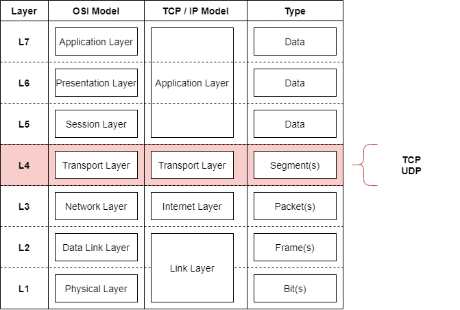
This layer sends segments of data between hosts. It uses the Layer 3 as the courier of these segments.
As the previous firewalling chapter already demonstrated us...
One of the most important part of the Transport Layer are the ports (or port numbers) of different services.
The port can be seen through many different representations
Example
[protocol]/[port]
tcp/22
udp/53
tcp/80
[application]://[ipv4 address]:[port]
http://192.168.0.1:80
https://192.168.0.5:443
ftp://192.168.0.5:21
Sometimes the application uses the default port defined by IANA: Service Name and Transport Protocol Port Number Registry
http://192.168.0.5/ is a completely valid address
The default port of HTTP is 80 (if search through IANA)
Thus, the browser typically leaves the :80 out of the URL.
services can be configured to other ports
e.g. http servers might be residing in http://192.168.0.5:8080
Now the default port of the HTTP server has been changed from 80 -> 8080
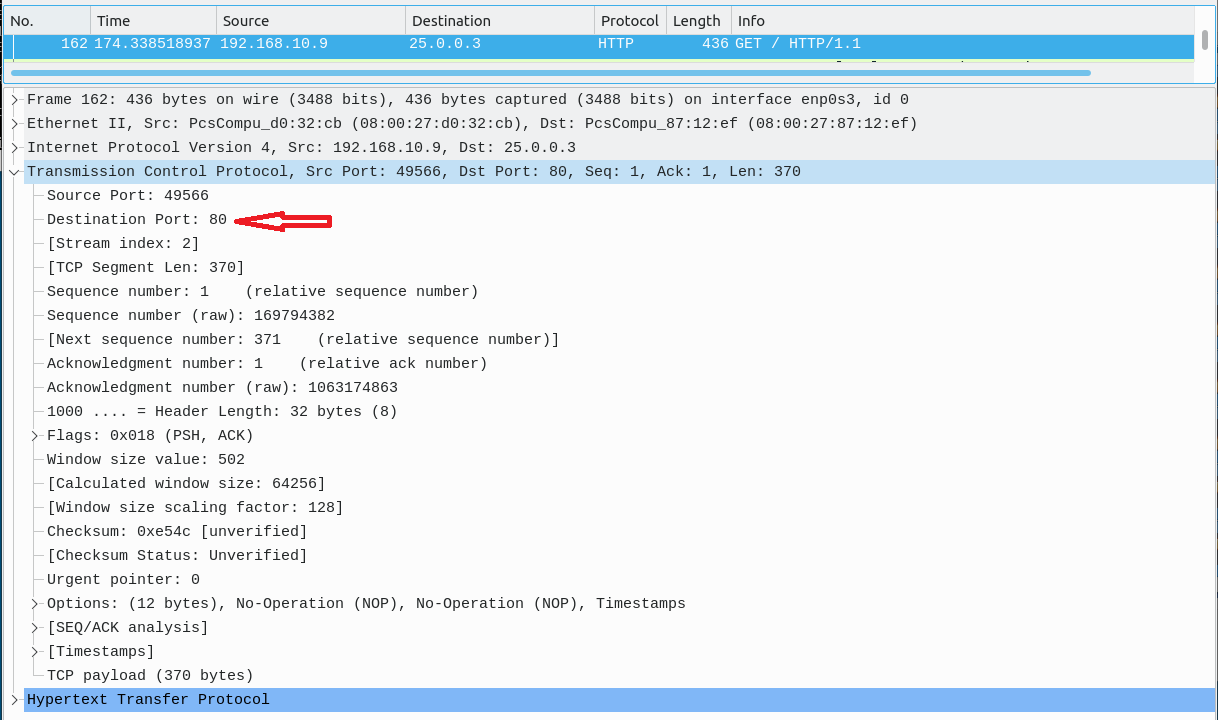
What is this port exactly? Well then we have to look at the segment headers...
Transmission Control Protocol - TCP
These videos are still in Finnish
Video: Data Networks, TCP, UDP and Controlling our Network Configuration (SSH, HTTP), part 2
TCP is a connection-oriented transmission protocol. It establishes connections between IPv4 addresses through the three-way handshake. It acknowledges received segments and in case of missing segments, adjusts the transmission speed (window size).
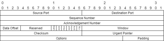
Lets look at the TCP header first.
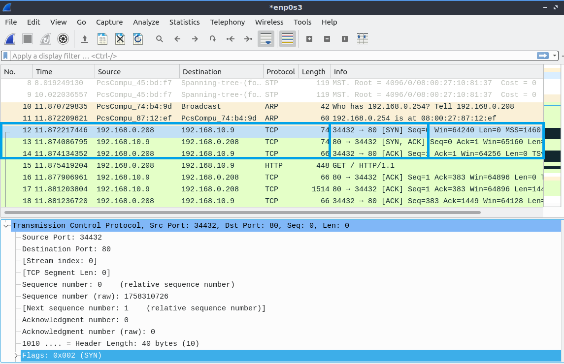
Wireshark of the TCP header in action
Source Port: 16 bits
The source port number. 2^16 = 0 - 65535 different ports. The client operating system listens to this port.
Destination Port: 16 bits
The destination port number. 2^16 = 0 - 65535 different ports. The server operating system listens to this port for client connections.
Sequence Number: 32 bits
As the header carries application data. The sequence number informs what section of that application data it is carrying. E.g. the first header could carry 0-999, second header could carry 1000-1999.
Acknowledgment Number: 32 bits
If the ACK flag (later) is set to 1. This field contains the value of the next sequence number the sender of the segment is expecting to receive. Once a connection is established this is always sent.
Data Offset: 4 bits
The number of 32 bit words in the TCP Header. This indicates where the data begins. The TCP header (even one including options) is an integral number of 32 bits long.
Reserved: 6 bits
For Future use. Usually zero.
Control Bits: 6 bits (from left to right):
Known as TCP Flags:
- URG: If true, read the Urgent Pointer
- ACK: If true, read the Acknowledgment field
- PSH: Push Function, sends the segment without waiting for additional bytestream from the application
- RST: Reset the (TCP) connection
- SYN: Synchronize sequence numbers
- FIN: No more data from sender
Window: 16 bits
This informs the amount of data which the sender of the header is willing to accept. Usually informed as "window size". Thus the next segment can be asked to contain 2000 bytes of data instead of 1000.
Checksum: 16 bits
Checksum verifies the integrity of the header. To eliminate the possibility of errors in transmission.
Urgent Pointer: 16 bits
The urgent pointer is a way for the TCP protocol to inform that there is "urgent data" coming through that has to be processed immediately. Unfortunately the implementations are wild
RFC6093 - On the Implementation of the TCP Urgent Mechanism
Unfortunately, virtually all TCP implementations process TCP urgent indications differently.
Options: variable
Because Options is a variable length field... it can support a variety of future needs.
Most notable examples are
- Maximum Segment Size (MSS) - How much data can be sent in a segment
- Timestamps - To support possible algorithms that require information on the jitter of the connection
- Selective Acknowledgements (SACK) - If there are segments that need to be acknowledged to have been received out of order
Padding: variable
Padding makes sure the TCP header is dividable by 32. So (e.g. 32 bit processors) can handle the header. Padding is just zero bits.
Handshaking
These videos are still in Finnish
Video: Data Networks, TCP, UDP and Controlling our Network Configuration (SSH, HTTP), part 3
One of the most important sections on connection establishment is the three-way handshake.
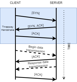
Same - As a wireshark packet capture
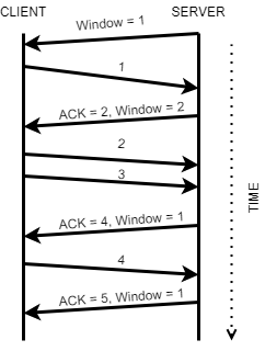
Windowing
Other important functionality is the reactiveness of TCP to possible transmission errors.
TCP can react to the changing transmission speeds in the network by increasing the segment size or decreasing the segment size. Additionally all the windows/segments have to be ACKonwledged as received.
User Datagram Protocol - UDP
These videos are still in Finnish
Video: Data Networks, TCP, UDP and Controlling our Network Configuration (SSH, HTTP), part 4
As TCP is a complicated and a protocol... full of fields and flags... fustrating.
User Datagram Protocol is a simple solution: "Send and forget!".
RFC 768 - User Datagram Protocol
- UDP provides a procedure for application programs to send messages to other programs with a minimum of protocol mechanism
- Delivery and duplicate protection are not guaranteed
- Applications requiring ordered reliable delivery of streams of data should use the Transmission Control Protocol (TCP)
Thus UDP is suitable of send & forget style of communication. The receiver will respond if necessary... thus typically retransmission timers are a problem of the Application Layer utilizing UDP.
I could tell you an UDP joke, but you wouldn't get it
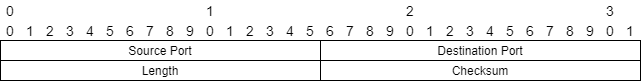
Source Port: 16 bits
The source port number. 2^16 = 0 - 65535 different ports.
It is optional, because replies are typically not expected. If unnecessary, source port = 0.
Destination Port: 16 bits
The destination port number. 2^16 = 0 - 65535 different ports.
Length
Length represents the total byte size of Header + Data.
Checksum
Checksum verifies the integrity of the header. To eliminate the possibility of errors in transmission.
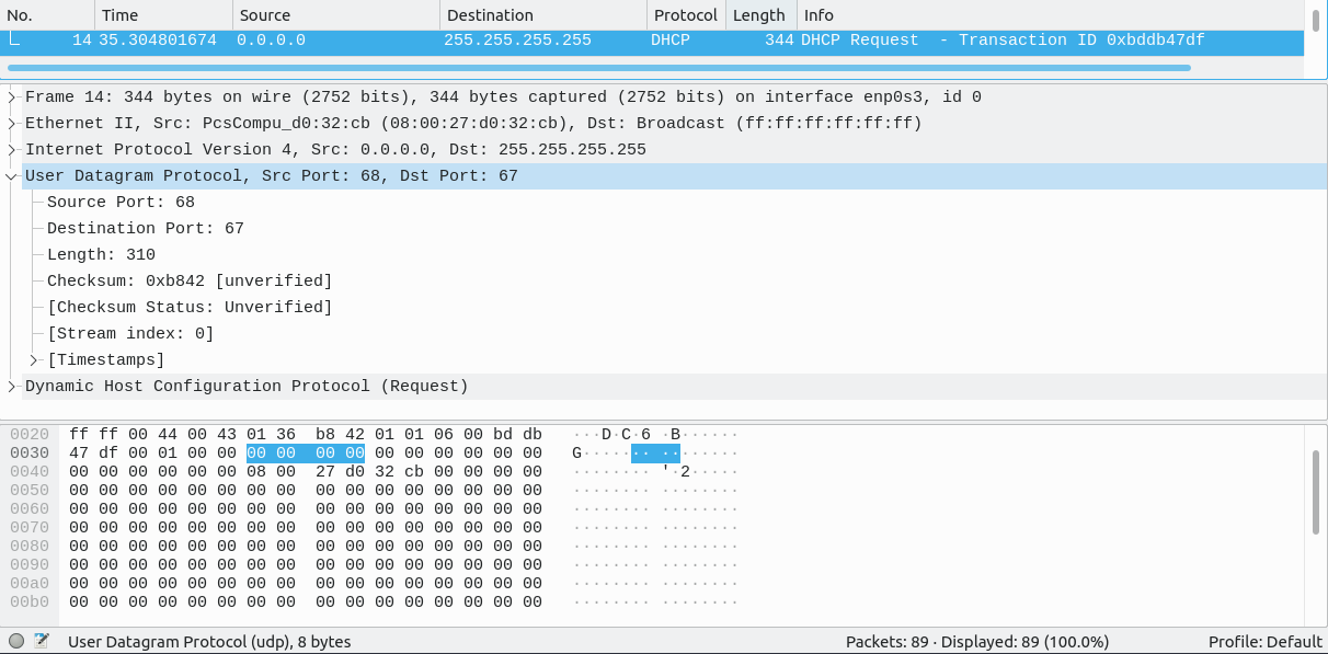
Wireshark of the UDP header in action
Reordering
Note that there are no Sequence Number in the UDP header. This means that if segments are received in the wrong order... there is no way to reassemble them.
Many telephony or videoconference solutions might use UDP transport, thus on top of UDP are two different protocols introduced to handle this "send simple, but reorder by squence number & timestamp".
- Real-time Transport Protocol - RTP
- Offers timestamping and sequence numbering
- Real-time Transport Control Protocol - RTCP
- Offers Quality of Service for the phone/video connection
Most recognizable ports that applications use
These videos are still in Finnish
Video: Data Networks, TCP, UDP and Controlling our Network Configuration (SSH, HTTP), part 5
TCP/UDP ports that all (IT-engineers) should recognize
You'll start to remember them, but don't worry. Exam questions will probably have a few of these as they are considered "common knowledge" in the field of IT
The list isn't in "importance" order, but in port number order.
| Service Name | Port Number | Transport Protocol | Description |
|---|---|---|---|
| FTP | 21 | tcp/udp | File Transfer Protocol |
| SSH | 22 | tcp/udp | The Secure Shell Protocol |
| Telnet | 23 | tcp/udp | Telnet |
| SMTP | 25 | tcp/udp | Simple Mail Transfer |
| DNS | 53 | tcp/udp | Domain Name Server |
| HTTP | 80 | tcp/udp | Hyper-Text Transfer Protocol |
| POP3 | 110 | tcp/udp | Post Office Protocol - Version 3 |
| SFTP | 115 | tcp/udp | Simple File Transfer Protocol |
| NTP | 123 | tcp/udp | Network Time Protocol |
| IMAP | 143 | tcp/udp | Internet Message Access Protocol |
| BGP | 179 | tcp/udp | Border Gateway Protocol |
| LDAP | 389 | tcp/udp | Lightweight Directory Access Protocol |
| HTTPS | 443 | tcp/udp | Hyper-Text Transfer Protocol - Secure |
| MySQL | 3306 | tcp | Open-source Structured Query Language |
| RDP | 3389 | tcp/udp | Remote Desktop Protocol |
Measuring TCP/UDP performance with iperf
iperf is a tool for measuring TCP/UDP bandwidth over a network. Our lubuntu.ovas have it installed.
The following has the Lubuntu VM on a bridged network (connected to the Internet)
Client -mode
iperf -c [ip address]
lubuntu@lubuntu-virtualbox:~$ iperf -c iperf.he.net -p 5201
------------------------------------------------------------
Client connecting to iperf.he.net, TCP port 5201
TCP window size: 85.0 KByte (default)
------------------------------------------------------------
[  3] local 192.168.0.208 port 57606 connected with 216.218.207.42 port 5201
[ ID] Interval       Transfer     Bandwidth
[  3]  0.0-10.1 sec  12.8 MBytes  10.6 Mbits/sec
lubuntu@lubuntu-virtualbox:~$
iperf -c [ipaddress] -p 5201
-p [port] defines the destination port of the connection
lubuntu@lubuntu-virtualbox:~$ iperf -c iperf.he.net -p 5201
------------------------------------------------------------
Client connecting to iperf.he.net, TCP port 5201
TCP window size: 85.0 KByte (default)
------------------------------------------------------------
[  3] local 192.168.0.208 port 57606 connected with 216.218.207.42 port 5201
[ ID] Interval       Transfer     Bandwidth
[  3]  0.0-10.1 sec  12.8 MBytes  10.6 Mbits/sec
lubuntu@lubuntu-virtualbox:~$
iperf -c [ipaddress] -p 5201 -t 50
-t [#] defines the time for testing in seconds
lubuntu@lubuntu-virtualbox:~$ iperf -c iperf.he.net -p 5201 -t 50
------------------------------------------------------------
Client connecting to iperf.he.net, TCP port 5201
TCP window size: 85.0 KByte (default)
------------------------------------------------------------
[  3] local 192.168.0.208 port 57604 connected with 216.218.207.42 port 5201
[ ID] Interval       Transfer     Bandwidth
[  3]  0.0-50.0 sec  58.9 MBytes  9.88 Mbits/sec
lubuntu@lubuntu-virtualbox:~$
iperf -c [ipaddress] -p 5201 -t 10 -i 2
-i [#] defines the interval of tests. 2 second intervals in this example during 10 second test period.
lubuntu@lubuntu-virtualbox:~$ iperf -c iperf.he.net -p 5201 -t 10 -i 2
------------------------------------------------------------
Client connecting to iperf.he.net, TCP port 5201
TCP window size: 85.0 KByte (default)
------------------------------------------------------------
[  3] local 192.168.0.208 port 57610 connected with 216.218.207.42 port 5201
[ ID] Interval       Transfer     Bandwidth
[  3]  0.0- 2.0 sec  2.88 MBytes  12.1 Mbits/sec
[  3]  2.0- 4.0 sec  2.75 MBytes  11.5 Mbits/sec
[  3]  4.0- 6.0 sec  2.75 MBytes  11.5 Mbits/sec
[  3]  6.0- 8.0 sec  2.00 MBytes  8.39 Mbits/sec
[  3]  8.0-10.0 sec  2.75 MBytes  11.5 Mbits/sec
[  3]  0.0-10.4 sec  13.1 MBytes  10.5 Mbits/sec
lubuntu@lubuntu-virtualbox:~$
iperf -c [ipaddress] -p 5201 -u
-u defines the iperf program to use UDP transmission.
lubuntu@lubuntu-virtualbox:~$ iperf -c iperf.he.net -p 5201 -u
------------------------------------------------------------
Client connecting to iperf.he.net, UDP port 5201
Sending 1470 byte datagrams, IPG target: 11215.21 us (kalman adjust)
UDP buffer size:  208 KByte (default)
------------------------------------------------------------
[  3] local 192.168.0.208 port 56028 connected with 216.218.207.42 port 5201
read failed: Connection refused
[  3] WARNING: did not receive ack of last datagram after 1 tries.
[ ID] Interval       Transfer     Bandwidth
[  3]  0.0-10.0 sec  1.25 MBytes  1.05 Mbits/sec
[  3] Sent 892 datagrams
lubuntu@lubuntu-virtualbox:~$
iperf -c [ipaddress] -p 5201 -u -b 1000000000
-b 1000000000 addition increases the max speed of UDP transmission to 1Gbit/s.
UDP is used in Denial of Service -attacks, thus DO NOT DO THIS IN THE INTERNET
It is forbidden in the Finnish law.
Rikoslaki 38 6 § Törkeä tietoliikenteen häirintä
Translation in english not applicable/doesn't uphold "the spirit of the law".
Server -mode
The following has the Lubuntu VM on a internal network (connected to the course data network)
The server model requires us to enable iperf in our laboratory environment. Notice that the traffic isn't routed through the firewall as it would require updates on the rule sets.
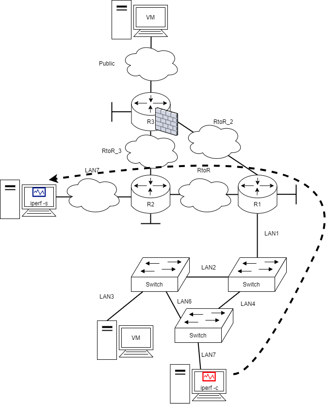
iperf -s on the lubuntu VM (server) on the left
Example:
lubuntu@lubuntu-virtualbox:~$ iperf -s
------------------------------------------------------------
Server listening on TCP port 5001
TCP window size:  128 KByte (default)
------------------------------------------------------------
iperf -s uses the ip address of the lubuntu which is 172.16.0.11 (used next on the client).
iperf -c 172.16.0.11 on the lubuntu VM (server) on the right
lubuntu@lubuntu-virtualbox:~$ sudo iperf -c 172.16.0.11
------------------------------------------------------------
Client connecting to 172.16.0.11, TCP port 5001
TCP window size:  289 KByte (default)
------------------------------------------------------------
[  3] local 192.168.10.9 port 35750 connected with 172.16.0.11 port 5001
[ ID] Interval       Transfer     Bandwidth
[  3]  0.0-10.0 sec   166 MBytes   139 Mbits/sec
The server at 172.16.0.11 reacts to this by
lubuntu@lubuntu-virtualbox:~$ iperf -s
------------------------------------------------------------
Server listening on TCP port 5001
TCP window size:  128 KByte (default)
------------------------------------------------------------
[  4] local 172.16.0.11 port 5001 connected with 192.168.10.9 port 35750
[ ID] Interval       Transfer     Bandwidth
[  4]  0.0-10.1 sec   166 MBytes   138 Mbits/sec
Network Configuration
These videos are still in Finnish
Video: Data Networks, TCP, UDP and Controlling our Network Configuration (SSH, HTTP), part 6
Through out the course we have handled network configuration on the network devices switch.ova and vyos.ova.
Network configuration is often a .cfg file or similar containing text.
Different configuration file examples
Cisco Systems configuration
https://www.cisco.com/c/m/en_us/techdoc/dc/reference/cli/n5k/commands/show-running-config.html
version 4.2(1)N2(1)
feature fcoe
feature telnet
feature tacacs+
feature udld
feature interface-vlan
feature lacp
feature vpc
feature lldp
feature fex
snmp-server enable traps entity fru
role name default-role
  description This is a system defined role and applies to all users.
  rule 5 permit command feature environment
  rule 4 permit command feature hardware
  rule 3 permit command feature module
  rule 2 permit command feature snmp
  rule 1 permit command feature system
role name praveena
username admin password 5 $1$VrQsB2KX$4jkUcx3sXWU8lhI1mlwLa/  role network-admin
username oregon password 5 $1$p3VJ0/BY$Kp22A08NeqCQ0asxUKXq91  role network-oper
ator
no password strength-check
ip domain-lookup
ip host switch 192.168.2.215
ip host BEND-1 192.168.2.215
tacacs-server host 192.168.2.54 key 7 "wawy1234"
aaa group server tacacs+ t1
    server 192.168.2.54
    use-vrf management
aaa group server tacacs+ tacacs
radius-server host 192.168.2.5 key 7 "KkwyCet" authentication accounting
aaa group server radius r1
    server 192.168.2.5
    use-vrf management
hostname switch
logging event link-status default
errdisable recovery interval 30
no errdisable detect cause link-flap
errdisable recovery cause pause-rate-limit
--More--
switch#
Paloalto configuration
https://knowledgebase.paloaltonetworks.com/KCSArticleDetail?id=kA10g000000Cm2lCAC
set network interface ethernet ethernet1/1 layer3 ip 10.18.143.145/26
set zone trust network layer3 ethernet1/1
set network virtual-router default interface ethernet1/1
set network interface ethernet ethernet1/2 layer3 ip 172.16.77.170/30
set zone untrust network layer3 ethernet1/2
set network virtual-router default interface ethernet1/2
set network virtual-router default routing-table ip static-route default destination 0.0.0.0/0 nexthop ip-address 172.16.77.169
set network profiles interface-management-profile allow_ping_ssh ping yes ssh yes
set network interface ethernet ethernet1/1 layer3 interface-management-profile allow_ping_ssh
set network profiles interface-management-profile allow_ping ping yes
set network interface ethernet ethernet1/2 layer3 interface-management-profile allow_ping
commit
Juniper Networks configuration
[edit]
interfaces {
    sp-2/0/0 { # This adaptive services interface creates the flow records.
        unit 0 {
            family inet {
                address 10.5.5.1/32 {
                    destination 10.5.5.2;
                }
            }
        }
    }
    fe-1/0/0 { # This is the interface where records are sent to the flow server.
        unit 0 {
            family inet {
                address 10.60.2.2/30;
            }
        }
    }
    ge-2/3/0 { # This is the input interface where all traffic enters the router.
        unit 0 {
            family inet {
                filter {
                    input catch_all; # This is where the firewall filter is applied.
                }
                address 10.1.1.1/20;
            }
        }
    }
    ge-3/0/0 { # This is the interface where the original traffic is forwarded.
        unit 0 {
            family inet {
                address 10.2.2.1/24;
            }
        }
    }
}
forwarding-options {
    sampling { # Traffic is sampled and sent to a flow server.
        input {
            rate 1; # Samples 1 out of x packets (here, a rate of 1 sample per packet).
        }
}
family inet {
    output {
        flow-server 10.60.2.1 { # The IP address and port of the flow server.
            port 2055;
            version 5; # Records are sent to the flow server using version 5 format.
            }
            flow-inactive-timeout 15;
            flow-active-timeout 60;
            interface sp-2/0/0 { # Adding an interface here enables PIC-based sampling.
            engine-id 5; # Engine statements are dynamic, but can be configured.
            engine-type 55;
            source-address 10.60.2.2; # You must configure this statement.
        }
    }
}
}
firewall {
    family inet {
        filter catch_all { # Apply this filter on the input interface.
            term default {
                then {
                    sample;
                    count counter1;
                    accept;
                }
            }
        }
    }
}
Controlling Devices
Console connection
The console connection is the oldest way to control a device. Network Devices typically have an con port for configuration. Console cables of the old are being replaced by USB ports. Anyway this way of giving the network device a shoulder to lean on (finnish: vierihoito) is the most basic way to install a device into a network to be reachable by SSH or HTTPS.
Cisco Router booted up while managed through through a blue console connection cable
On this course the console connection is used through VirtualBox Console window to the Virtual Machines.
Remote connections
There are different ways to configure a network device through the network. These connections are called:
- In-Band connection
- Out-of-Band connection (OOB)
In-Band connection is how we configure devices on this course (excluding VirtualBox console).
Out-of-Band connection is how network devices are configured in high-availability networks to ensure connection to the devices ... even in network changes. This means that there is another data network for the management connection ... network.
But how are the OOB network devices configured
Well "Who will guard the guards themselves?"
Typically one layer of separation is enough. Very rarely connection problems affect both networks (given the premesis that the networks use different physical cabling also)
Naming devices
Well... this is an hard one. Throughout the course I've used variable different names for the Routers. When remotely connecting, the device naming should be apparent in the console.
Naming in Vyos (Routers)
Vyos: set system host-name [name]
Requires a full reboot of the devices to take affect.....
Naming in EXOS (Switches)
EXOS-VM.1# configure snmp sysName [name]
SSH
Secure Shell (SSH) is an application and a protocol to connect to your server (or network device) from afar to administer it (by opening a shell/command-line interface)
SSH provides an encrypted connection through TCP/IP -networks to securely operate a device (be it server/switch/router/...).
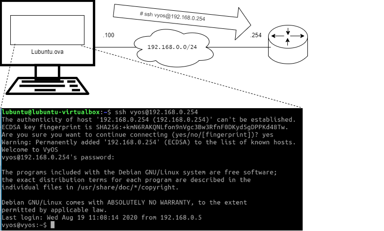
It is de facto tool of any IT administrator.
To enable SSH server in switch.ova:
EXOS-VM.8 # enable ssh2 port 22
WARNING: Generating new server host key
This could take up to 1 minute and cannot be cancelled. Continue? (y/N) Yes

Key Generated.
EXOS-VM.9 #
To enable SSH server in vyos.ova:
vyos$vyos# set service ssh port 22
vyos$vyos# commit
vyos$vyos# save
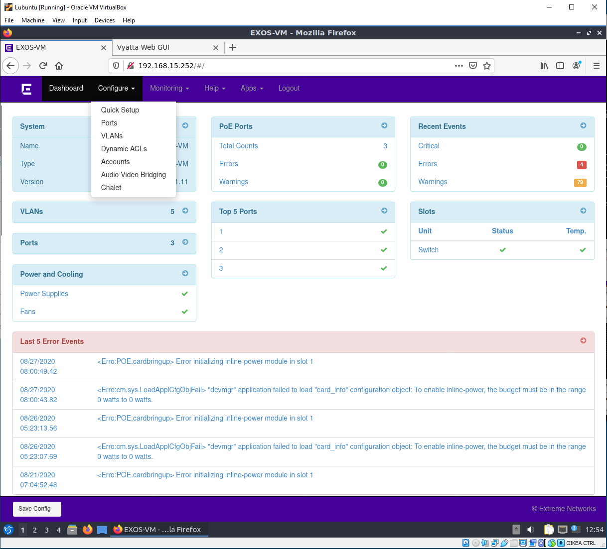
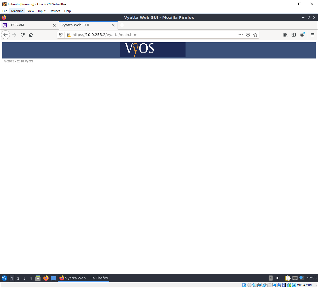
HTTP(S)
Very often somekind of a web server interface is implemented in commercial software. This is a nice front-end for users who do not understand what they are doing, but now they don't need to learn CLI -commands (which is what we have been doing on the course) to get into the "dirty details" of operations.
Once you've understood how the commands work under the hood. HTTP might be a way to quickly configure devices. Sometimes it is actually the only way... leaving engineers... fustrated.
HTTP server(s) can be enabled on the device(s).
Switch: EXOS-VM.1# enable web http
Router (vyos): set service https listen-address [IPv4 address on the Router - e.g. loopback]
how do you save a webpage configuration!?
Well you don't... typically the webpages offer somekind of a solution to download the configuration text file...
Application Programmable Interfaces - API
Network Automation is increasing the possibility to have e.g. python scripts configure the device... or running on the device.
- python-vyos-mgmt -library for Vyos devices
- ExtremeScripting
Network Automation has required Operations to interact with Development to form "DevOps". Typically this means automation is improved through git -version control which contains the configuration files for deployment by Continuous Integration - Continuous Development (or CI/CD) pipelines.
Five stages of Network Automation Grief - ipspace.net
Denial. I don’t need automation. Our network doesn’t change that much, and it’s perfectly OK to configure devices by hand. We’ve always been doing it this way, and it was fine.
Anger. Why is everyone talking about this new stuff? Why should I learn something new after studying networking for a decade?
Bargaining. Maybe I don’t need automation. Maybe I can buy an intent-based or software-defined product from my $vendor and continue using GUI… or maybe I could do a bit of Google-and-paste and get something done.
Needless to say, $vendors love engineers being stuck in this phase… and well-meaning evangelists explaining how easy it is to automate stuff (without ever telling you about the hard parts like source-of-truth or data models) inadvertently help creating either Expert Beginners that stay stuck at this phase forever (while thinking they really nailed it) or death by a thousand scripts.
Depression. It’s so complex. I have to learn all this new stuff. I hate YAML. Jinja2 is really a pile of crap. Network devices suck… even SSH doesn’t work reliably. Why couldn’t my $vendor give me a clean API returning the data I need (hint: because you chose the wrong vendor ;).
Acceptance. Damn it, I’m an engineer. I can make it work. I’ll work hard, master new stuff, and get it done. After all, if I managed to get to the point where I can design and deploy complex networks, I might be able to team with a programmer (or an automation expert) and slowly build something useful.
- Source: blog.ipspace.net ... this is an awesome blog for data networking... highly recommended
This automation is a part of Fundamentals of Scripting and automatization -course.
Configuration Control
By now you must have noticed the differences between the switch.ova (EXOS) and vyos.ova (Vyos) operating systems.
- The
vyos.ovahas to havecommitinserted to take configuration into use - The
switch.ovatakes the commands ... immediately into use
Cisco Systems has established namings for these configurations as
Running configuration- the configuration that is currently operational on the deviceStartup configuration- the configuration saved on the device (from which the system boots)
Configuration Rollbacks are a way to restore the configuration to an earlier point (usually a working configuration).
Configuration Rollbacks - Our routers support this phenomenon.
vyos@vyos2# rollback
Possible completions:
  <N>   Rollback to revision N (currently requires reboot)

  Revisions:
    0   2020-08-27 10:22:43 vyos by cli
    1   2020-08-27 09:53:21 vyos by cli
    2   2020-08-21 07:22:18 vyos by cli
    3   2020-08-21 07:11:22 vyos by cli
    4   2020-08-19 05:34:12 vyos by cli
    5   2020-08-19 05:30:44 vyos by cli
    6   2020-08-12 09:22:18 vyos by cli
    7   2020-08-06 05:12:57 vyos by cli
    8   2020-08-06 05:08:18 root by boot-config-loader
    9   2020-08-05 10:11:31 vyos by cli
    10  2020-08-05 09:33:52 vyos by cli
    11  2020-06-01 12:04:55 root by boot-config-loader
    12  2020-06-01 12:04:54 root by init

[edit]
vyos@vyos2#
Continue to the Exercises
 E12 Controlling Network Configuration
Back to the Schedule?
License
This course and its materials are written by Karo Saharinen and licenced by Attribution-NonCommercial-NoDerivatives 4.0 International (CC BY-NC-ND 4.0) license.
